DIY Master Audio Stepped Attenuator A/B Switcher
Last Update 08-15-2025
This DIY stepped attenuator became a necessity when I wore out the
master volume control on my line mixer to the studio monitor
speakers. That part is no longer available so I stopped using
those master volume controls. The attenuator is the stepped
type that includes compensation of frequencies according to the well
known Flescher-Munson loudness curve of the human ear. The
multi-ganged 24T4P rotary switch (4 poles for stereo balanced lines)
will last much longer than those volume controls.
The A/B switcher became a necessity because my studio had grown such
that I have two locations from where I build songs. One is the
MIDI station where all my keyboards, modules and DAW computer are,
the other is at the Mixing station where the mixer, hard disk
recorder, and processors are. Most studios would use two sets
of monitor speakers; I only needed one set because the speakers
rotate at the keyboard stand, pointing to where I am working.
The keyboard stand with speakers is strategically placed so they are
close to the near-field listening range of the speakers whether I
work at the MIDI station or the Mixing station. Saves wiring,
and saves the expense of an extra power amplifier and speakers.
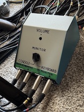
Picture the A/B switcher as a 2x2 matrix switcher, with console
input/output on one axis and keyboard/monitor on the other
axis. All I/O are stereo balanced differential lines. I
need two configurations for the switcher. One is when sitting
at the Mixing station I want keyboard outputs routed to inputs on
the mixer, then mixer outputs routed to the monitors. The
other is sitting at the MIDI station, I want keyboard outputs routed
to monitors and no mixer routing.
For clarity I used chrome plated jacks for stereo left and black
ones for stereo right. A single rotary switch does the matrix
switching. The matrix relative to the rotary switch is
actually 8x8 - 4 sets of stereo L/R lines each which are dual
balanced differential wires. Thus I acquired a 8P2T rotary
switch for the job, break-before-make as I wanted to avoid any
feedback loop squeal between switch states.
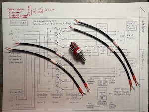
In the image above, rotary switch and sample cables are shown before
assembly. Cable prep involved not just trimming the wires but
labeling the cable, so that when the jacks are connected I know
which ones are which. The raw cables are Canare L-2B2AT that I
acquired from Redco. It is lightweight low profile cable for
fixed installations (IE rack wiring) and is very easy to work
with for assembly. I have been using that cable in my studio
and stage systems for over twenty years and have yet to find a
broken cable. I have a long established convention of wiring
the white wire to pin 2 (hot) of the XLR interconnect and the orange
wire to pin 3. To avoid ground loops I do not route shield
(shield wires are not "ground" and only need connection at one end)
or chassis on the jacks (shield from the monitor amp is used for
ground at the attenuator network circuit). This keeps
everything straight and retains the hair on my head!
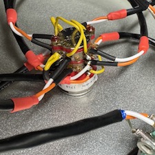
The next image above is a close-up of the wiring of the rotary
switch. This is where I had to be really careful against
wiring errors, and there were a few occasions I caught myself making
an error. I used shrink wrap tubing at the switch terminals to
minimize flexing of the wires and prevent breakage. Not
anxious to fix a broken wire in that rats' nest!!
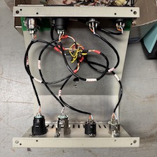
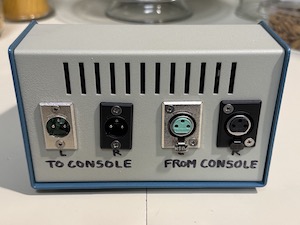
Next image shows the assembled matrix switch box (I have not yet
assembled the stepped attenuator). The jacks had to be
oriented upside down or sideways (hey I didn't design this thing to
be pretty) so with the hood open I could access the set screws that
secure the connector inlet. These inlets need to be removed
for wire assembly. Next is testing - it worked right out of
the gate. Preparation is a big part in assembly!!!
The next project is building the stepped attenuator assembly, which
will be a bitch but there were good reasons for this choice. I
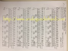
chose the stepped attenuator design that I found in one of my
engineering books (Audio Cyclopedia by Howard M Tremaine). The
attenuation network is not only a multi-tap voltage divider it also
includes filter networks to simulate the Flescher-Munson loudness
curve that maps the relative loudness of the human ear over the
frequency range. The frequency response of the human ears
between loud and soft volume is not flat!
Why not a simple variable potentiometer? It is bad practice to
use a variable potentiometer for stereo volume control - this
requires a ganged audio taper potentiometer. The forming of
the taper of each gang layer is not consistent from layer to layer
during fabrication so there is no guarantee that all mechanical
positions of each layer will be the same resistive value. Bad
news with differential signals as this will cause stereo image shift
and alter the tone of the signal (big no-no in a studio). And
we're asking precise attenuation with balanced signals of stereo
pairs, requiring four ganged potentiometer - forget it!
By using precision resistors and tight tolerance capacitors in the
attenuator networks, the attenuation between all four signals is
consistent enough that image shifting will be minimized. The
human ear is not sensitive to volume differences, the best it can
detect is a 2dB change. The precision of this attenuator
network from gang to gang is 2dB. The metal film resistors are
military grade low noise types, same ones used in professional audio
equipment. The polystyrene capacitors have a very low
temperature factor, meaning their values vary the least over a wide
temperature range. These capacitors also have low absorption
factor meaning that they drain almost all their electrical charge
when they are discharged. To minimize image shift in the
stereo field, these are important parameters for critical tuned RC
networks such as multi-ganged stepped attenuators especially those
with non-linear frequenty contours.
Stepped attenuators are found in professional audio devices and
broadcast systems. The stepped attenuator has one big
disadvantage - it requires a 20+ position rotary switch with four
poles. These are not easy to find and they are not
cheap. Fortunately I happened upon a NOS supply of 24T4P
rotary switches so I bought a few to last me for life. As a
bonus, the switch contacts are sealed and gold plated for maximum
conductivity. Rotary switches enjoy one big advantage over
variable potentiometers - they have a much longer life.
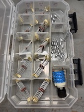
Assembly of the stepped attenuator is going to be a bitch. In
the 2nd row of images above, the rotary switch and bins of
resistors/capacitors are shown. The attenuator is going to be
built on the rotary switch which is how they are assembled in professional audio devices.
By placing the components on the switch (and not on a separate
circuit board with extended wiring), you greatly minimize inductance
of connecting wires and EMI of bundled cabling. Stray
inductance affects the tuned RC networks and are not very welcome!
Once this is assembled then it will be installed in the matrix
switch box to control the audio level going to the monitors, and
that completes the DIY project. It may take a while...

Home
